Raspberry Pi Pico 2(RP2350)’s I2C
Now that you understand the basics of the I2C protocol, let us look at how it works on the Raspberry Pi Pico 2. The RP2350 has two separate I2C controllers, named I2C0 and I2C1. Think of these as two independent communication channels that can operate simultaneously. This helps when two devices share the same I2C address, because you can place them on separate controllers.
Available I2C Pins
Both I2C controllers support multiple pin options for SDA and SCL. You only choose one pair for each controller.
| I2C Controller | GPIO Pins |
|---|---|
| I2C0 - SDA | GP0, GP4, GP8, GP12, GP16, GP20 |
| I2C0 - SCL | GP1, GP5, GP9, GP13, GP17, GP21 |
| I2C1 - SDA | GP2, GP6, GP10, GP14, GP18, GP26 |
| I2C1 - SCL | GP3, GP7, GP11, GP15, GP19, GP27 |
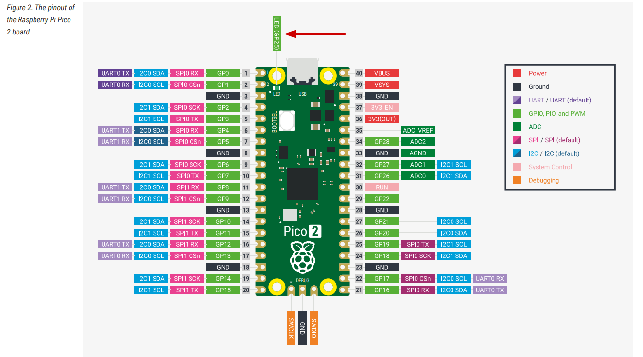
On the Pico 2 board layout, pins that support I2C functionality are labeled with SDA and SCL, and are also highlighted in blue to make them easy to identify.
Speed Options
The RP2350’s I2C controllers support three different speed modes, allowing you to match the capabilities of whatever devices you’re connecting:
- Standard mode: Up to 100 kb/s (kilobits per second) - the slowest but most universally compatible
- Fast mode: Up to 400 kb/s - a good balance for most sensors and displays
- Fast mode plus: Up to 1000 kb/s - for when you need quicker data transfer
It’s worth noting that the RP2350 doesn’t support the ultra-high-speed modes (High-speed at 3.4 Mb/s or Ultra-Fast at 5 Mb/s) that some specialized devices use. However, most common sensors, displays, and peripherals work perfectly fine within the supported speed ranges.
Controller or Target mode
The RP2350 can only be a Controller (master) or a Target (slave) at any given time—not both simultaneously on the same controller. For typical projects where the Pico 2 is controlling sensors and displays, you’ll always use controller mode.
For the complete technical specifications, you can refer to page 983 of the RP2350 Datasheet.