How Servo Control Works
A servo motor uses PWM (Pulse Width Modulation) signals to control its position. The width of each pulse tells the servo which angle to move to, and continuously repeating that pulse keeps it there.
Basic Operation
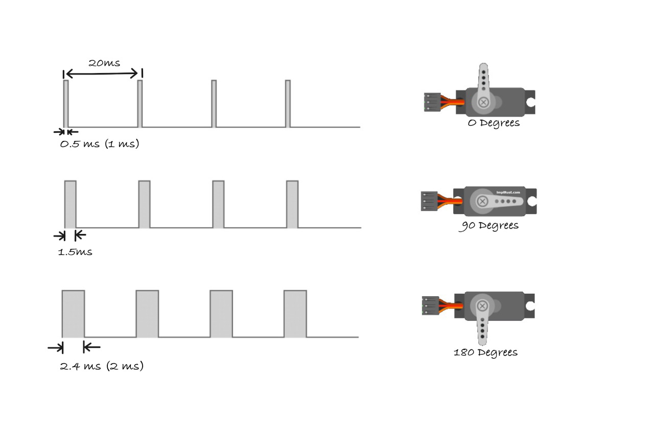
Servos operate on a 50Hz frequency, meaning they expect a control pulse every 20 milliseconds. Within each 20ms cycle, the duration that the signal stays high determines the servo’s position.
Think of it like this: every 20ms, you send the servo a brief instruction. That instruction’s length tells the servo where to point.
Pulse Width
The position of the servo is controlled by how long the signal pulse stays high. A short pulse moves it to the minimum position (typically 0°), a medium pulse moves it to center (typically 90°), and a long pulse moves it to the maximum position (typically 180°).
Standard vs. Reality
You’ll often see these “standard” values referenced: 1.0ms pulse for 0°, 1.5ms pulse for 90°, and 2.0ms pulse for 180°. However, cheap servos rarely follow these numbers exactly. Manufacturing variations mean each servo has its own characteristics.
For example, my servo required 0.5ms for minimum position, 1.5ms for center, and 2.4ms for maximum position. This is completely normal and expected.
Treat published pulse widths as starting points, not absolute values. Always test and calibrate your specific servo. A logic analyzer or oscilloscope helps, but simple trial and error works fine too. The examples in this guide use values that worked for my servo, so you may need to adjust them for yours.
Calculating Duty Cycle
The duty cycle represents the percentage of time the signal stays high during each 20ms cycle. Understanding this helps you configure PWM correctly in your code.
Example Calculations
For a 0.5ms pulse (0° position), the duty cycle is calculated as:
A 0.5ms pulse means the signal is “high” for 0.5 milliseconds within each 20ms cycle. The servo interprets this as a command to move to the 0-degree position.
\[ \text{Duty Cycle (%)} = \frac{0.5 \text{ms}}{20 \text{ms}} \times 100 = 2.5\% \]
This means that for just 2.5% of each 20ms cycle, the signal stays “high” causing the servo to rotate to the 0-degree position.
For a 1.5ms pulse (90° position), the calculation gives us:
A 1.5ms pulse means the signal is “high” for 1.5 milliseconds in the 20ms cycle. The servo moves to its neutral position, around 90 degrees (middle position).
\[ \text{Duty Cycle (%)} = \frac{1.5 \text{ms}}{20 \text{ms}} \times 100 = 7.5\% \]
Here, the signal stays “high” for 7.5% of the cycle, which positions the servo at 90 degrees (neutral).
For a 2.4ms pulse (180° position), we get:
A 2.4ms pulse means the signal is “high” for 2.4 milliseconds in the 20ms cycle. The servo will move to its maximum position, typically 180 degrees (full rotation to one side).
\[ \text{Duty Cycle (%)} = \frac{2.4 \text{ms}}{20 \text{ms}} \times 100 = 12\% \]
In this case, the signal is “high” for 12% of the cycle, which causes the servo to rotate to 180 degrees.