Servo with Raspberry Pi Pico 2 (RP2350)
The required power supply and pulse width can vary depending on the servo motor you use, so it is always best to check the datasheet or product specifications. The servo I am using operates in the 4.8V to 6V range, so I will power it with 5V.
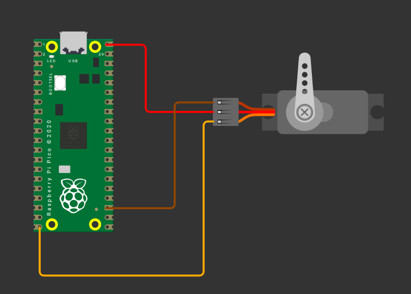
- Ground (GND): Connect the servo’s GND pin (typically the brown wire, though it may vary) to any ground pin on the Pico 2.
- Power (VCC): Connect the servo’s VCC pin (usually the red wire) to the Pico 2’s 5V power pin(VBUS).
- Signal (PWM): Connect the servo’s control (signal) pin to GPIO15 on the Pico 2, configured for PWM. This is commonly the orange wire (may vary).
| Pico Pin | Wire | Servo Motor | Notes |
|---|---|---|---|
| VBUS |
|
Power (Red Wire) | Supplies 5V power to the servo. |
| GND |
|
Ground (Brown Wire) | Connects to ground. |
| GPIO 15 |
|
Signal (Orange/yellow Wire) | Receives PWM signal to control the servo's position. |